Understanding your Potentiostat and its Limitations
How to Read Spec Sheets, Ask the Right Questions, and Choose the Right Tool for Your Electrochemical Experiments
When it comes to electrochemistry, your data is only as good as your setup — and at the heart of many experiments lies the potentiostat. But while these instruments are critical to accurate measurements, spec sheets can often feel like a wall of jargon: compliance voltage, slew rate, current ranges… what does it all actually mean?
In this post, we’ll break down the key specifications of potentiostats, explain how these parameters impact your experiments, and guide you on how to interpret these specs to avoid the common pitfall of buying more instrument than you need — or worse, one that can’t handle your application at all.
Why Understanding Your Potentiostat Matters
A potentiostat isn’t just a black box between your electrodes and your laptop. It’s an active part of the measurement process — controlling the potential, monitoring the current, and, crucially, limiting what you can and can’t measure.
It’s worth remembering:
Good experimental design isn’t about using the most powerful potentiostat. It’s about using the right one for your system.
Whether you're studying enzyme kinetics, corrosion processes, battery electrodes, or biosensors, understanding your instrument’s specifications is as important as understanding the electrochemistry itself.
The Anatomy of a Potentiostat: What’s Inside the Box?
At the heart of potentiostat operation is the three-electrode system, which allows precise control over the potential at the Working Electrode (WE) while independently measuring the current flow through the Counter Electrode (CE). This setup prevents issues with unstable or drifting reference potentials, which can occur in simpler two-electrode systems.
But what actually happens inside the potentiostat to make this control possible? Let’s break down both the electrode configuration and the internal electronics that manage this process.
The Three-Electrode System: Purpose and Function
A three-electrode configuration includes:
1. Working Electrode (WE)
This is the site of your electrochemical reaction — whether that’s a redox process, corrosion event, electrodeposition, or biosensor signal generation. The potentiostat regulates the potential of the WE relative to the Reference Electrode.
2. Reference Electrode (RE)
The RE provides a stable potential against which the WE is controlled. Crucially, the Reference Electrode should pass virtually no current to avoid potential drift.
Some systems include a Working Sense lead, a separate line that ensures accurate potential measurement directly at the WE without any potential drop along the connection lead (especially important when working with high currents or long cables).
3. Counter Electrode (CE)
The CE completes the electrical circuit and is responsible for carrying the current required to balance the reactions occurring at the WE. The Control Amplifier inside the potentiostat uses the CE to adjust current flow in real time, maintaining the correct WE potential.
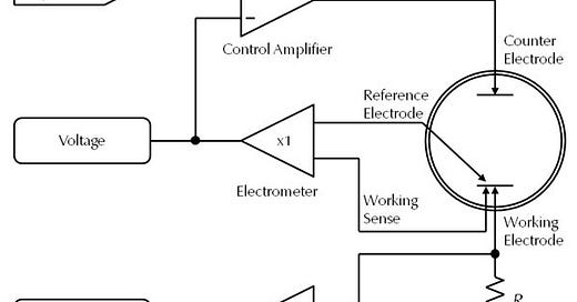
The operation of a potentiostat is governed by its internal electronics, all of which are shown in your diagram. Here’s how they work together:
1. Signal Generator
This component creates the input waveform requested by the user. Whether you’re applying a constant potential (potentiostatic mode), a linear ramp (cyclic voltammetry), or an alternating signal (for impedance spectroscopy), the Signal Generator defines the shape and timing of that input.
2. Control Amplifier (CA)
The Control Amplifier is the core of the potentiostat’s feedback loop. It continuously compares the measured potential between the Reference Electrode and Working Sense lead to the desired signal from the generator.
If there’s any deviation between the measured and setpoint potentials, the amplifier adjusts the current flowing through the Counter Electrode to bring the system back to the target potential.
3. Electrometer (Voltage Measurement Unit)
The Electrometer measures the potential difference between the Working Sense and Reference Electrode with extremely high input impedance to minimise current draw. This prevents polarisation of the Reference Electrode and ensures that the measured potential accurately reflects the true conditions at the WE.
Often includes a gain setting of x1 (unity gain) for precise measurement without amplification.
High input impedance (GΩ to TΩ) keeps the RE stable.
4. Current-to-Voltage Converter (I/E Converter)
The I/E Converter is responsible for measuring the current flowing through the cell. It works by converting the current into a voltage signal using a resistor, commonly labelled Rm in potentiostat diagrams (as in your provided schematic).
The voltage drop (ΔU) across ‘Rm’ is directly proportional to the cell current (Ohm’s Law).
Gain of x1 typically used here as well.
The potentiostat may switch between different resistor values (current ranges) depending on the expected current level.
5. Measurement Resistor (Rm)
The resistor Rm is a crucial part of the current measurement circuit. Different values of Rm allow the potentiostat to select between different current ranges (low current = high resistance; high current = low resistance).
Large resistors improve sensitivity for low currents but introduce more thermal noise.
Small resistors allow high current measurement but reduce sensitivity at the low-current end.
How These Components Work Together: The Feedback Control Principle
The potentiostat operates using a closed-loop negative feedback system:
Signal Generator defines the desired potential.
Electrometer measures the actual potential between the Working Sense and Reference Electrode.
Control Amplifier compares the measured value to the setpoint.
If the two don’t match, the Control Amplifier adjusts the current at the Counter Electrode until the measured potential equals the desired input.
Meanwhile, the I/E Converter and Rm handle current measurement for data recording.
This loop runs continuously throughout your experiment, allowing for real-time control and adjustment.
Key Specifications (and Why They Matter)
This section breaks down the key specifications that determine what your potentiostat can (and can’t) do, so you can make informed decisions and avoid costly mistakes.
1. Maximum Current: Don’t Pay for What You Don’t Need
Maximum current refers to the highest current the potentiostat can supply or measure. This specification directly influences the design of the current measurement circuitry, particularly the values of the measurement resistors (Rm) in the I/E Converter.
Key Point: High current capability often comes at the expense of low current precision. More powerful amplifiers and lower-value resistors are required to handle large currents — but these can introduce higher noise and reduce sensitivity at the microampere or nanoampere level.
When High Current Is Necessary:
Battery research
Fuel cells
Electroplating
When Low Current Precision Is Critical:
Biosensors
Corrosion studies
Coatings and insulation monitoring
Organic electronics
⚠️ Caution: Over specifying current range “just in case” can lead to poor signal resolution where it matters most.
2. Current Ranges and Gain Settings: Precision Over Power
The potentiostat achieves flexible current measurement by switching between different current ranges, each defined by a different resistor value (Rm) in the I/E Converter. These ranges allow accurate current measurements from picoamperes to amperes — but only if the correct range is chosen.
Correct range: Maximises signal-to-noise ratio.
Too high: Buries the signal in noise.
Too low: Causes signal clipping or overload.
Some systems offer auto-ranging, which selects the optimal range dynamically. However, for sensitive experiments (e.g., biosensing or EIS at low currents), manual fixed ranges are often preferred to ensure consistent performance.
Internal Gain:
Low-current ranges may also use internal amplification (e.g., ×10 or ×100 gain) to improve signal detection. Be aware that this also amplifies noise — so always ensure your shielding (e.g., Faraday cage) is appropriate.
3. Maximum Applied Potential vs. Compliance Voltage: Not the Same Thing
These two specifications are frequently confused but serve very different roles:
If your experiment requires a large potential drop across a high-resistance cell, insufficient compliance voltage means the system won’t be able to maintain your set potential — leading to CA overload warnings or data failure.
4. Rise Time, Slew Rate, and Bandwidth: Speed vs. Stability
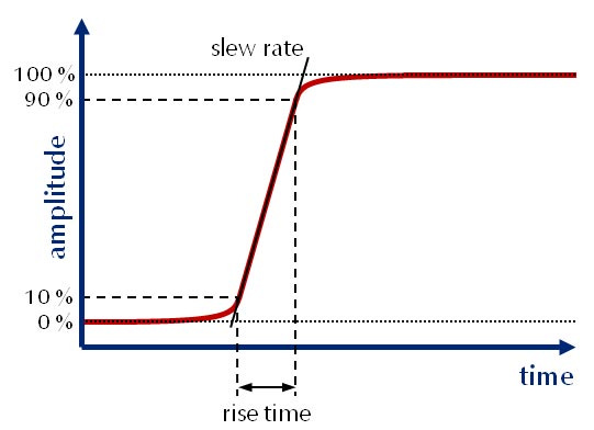
Rise Time: How quickly the output signal rises from 10% to 90% of its final value.
Slew Rate: The steepest slope at which the signal can change (V/s).
Bandwidth: The frequency at which the amplifier gain drops to unity (1). Related to how fast the system can respond to AC signals.
Common Misunderstanding: Faster is not always better. High-speed settings may lead to overshoot, ringing, or oscillation, especially in capacitive systems (like coatings or biosensors).
The Control Amplifier (CA) speed settings balance these trade-offs:
High speed: Fast response, risk of instability.
Low speed: Greater stability, slower response.
5. Electrometer Input Current and Impedance: The Silent Guardians of Accuracy
The Electrometer's job is to measure the WE-RE potential without disturbing the system. To do this effectively:
Input Current: Must be as close to zero as possible (picoampere range).
Input Impedance: Should be high (GΩ to TΩ) to prevent leakage currents and preserve potential stability.
This is especially critical when working with:
High-impedance coatings
Thin films
Corrosion monitoring
Electrochemical impedance spectroscopy (EIS)
Pro Tip: Always use proper shielding (Faraday cage) and short cables to minimise noise when operating in low-current, high-impedance regimes.
If you find this content valuable and would like to keep reading consider becoming a paid subscriber. For just £3.50/month, you'll unlock full access to everything Electrochemical Insights has to offer.


